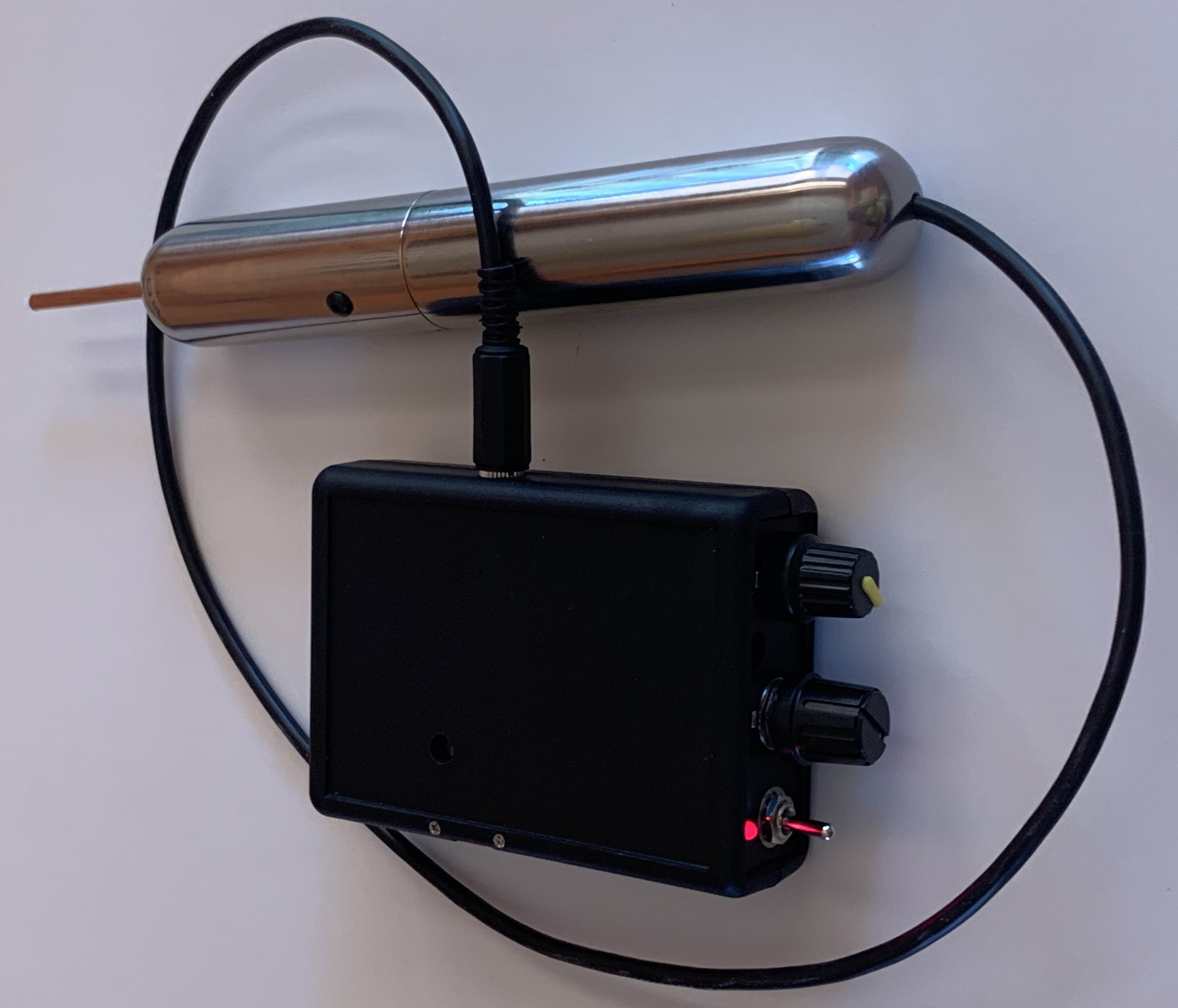
Figure 1
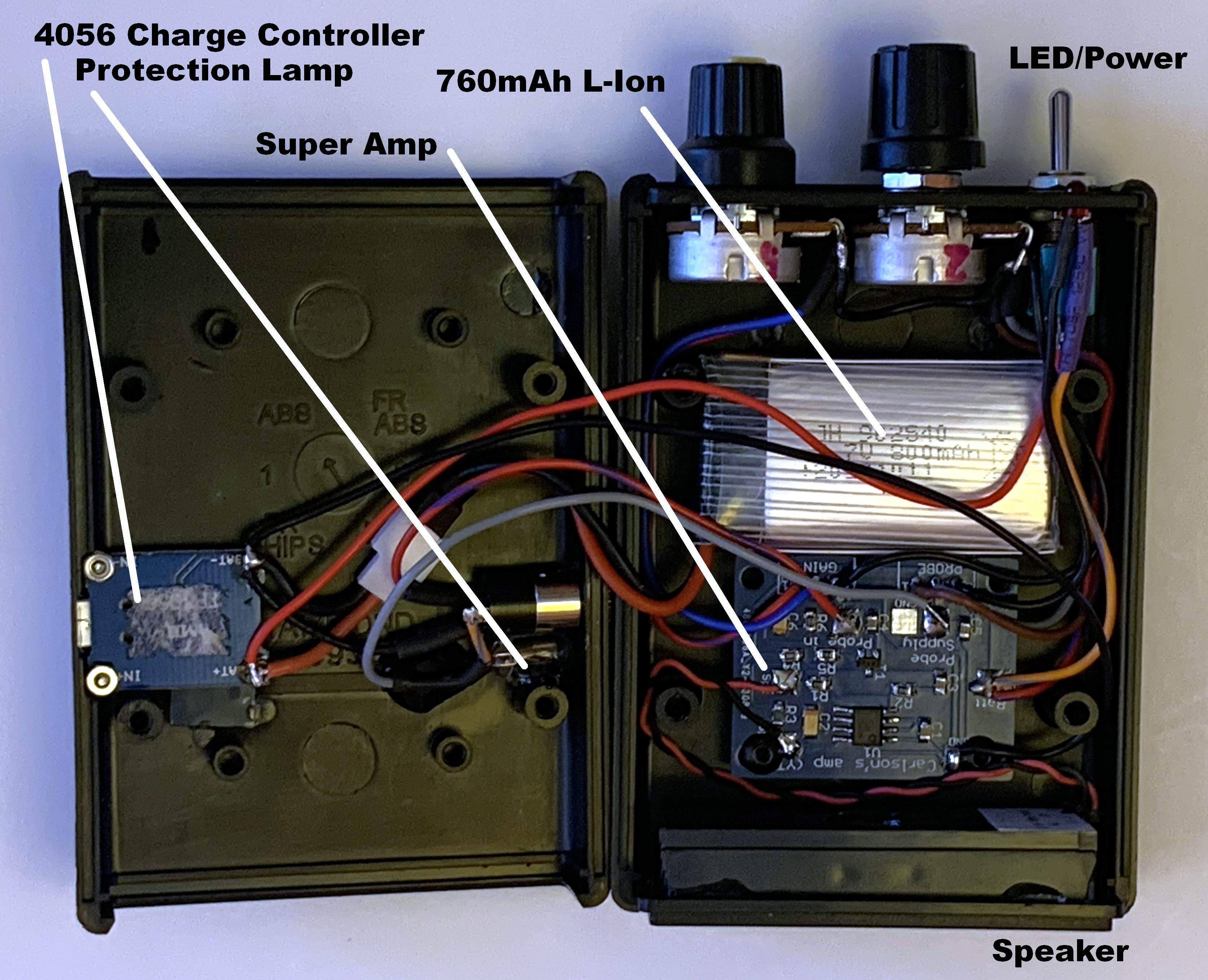
 Figure 2
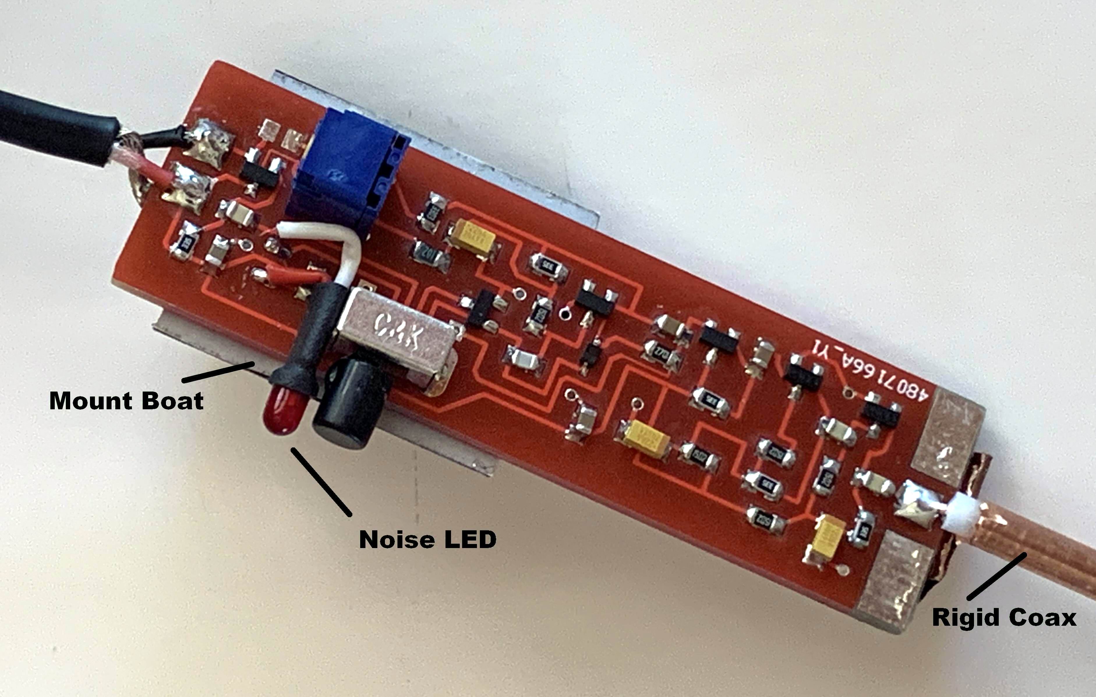
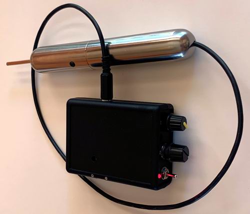 Figure 3
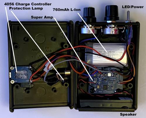 Figure 4
|
All NEW PCB Design!
MK0 Kit Get Your Own Parts
As seen on YouTube and commented on many other sites, Paul Carlson designed a very useful non-contact
very high gain electronic probe for investigating just about any kind of electrical signal from audio to RF.
The design is well proven and open-sourced. There are also several open-source PCB designs for the probe and
amplifier, but most of them are SMD designs. This is likely the primary barrier to building a one-off
implementation of this design.
We have produced an all new PCB set design with improved component layout, improved peripheral component attachment
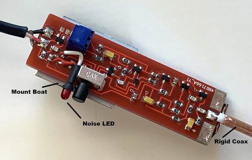
and improved the POP noise LED operation. Here is a list of the changes:
Probe PCB:
- The POP noise LED is powered by a 4th cable wire allowing a constant LED supply voltage.
- The POP noise LED driver is changed to a N-channel MOSFET for improved drive performance.
- An additional emitter-follower output buffer is added to the amplifier PCB for optionally driving a meter
or scope or external amplifier.
- All horizontal component layout.
Amplifier PCB:
- The R7 POT overload incandescent lamp is not mounted on the PCB.
- The amplifier power switch has dedicated terminals on the PCB.
- The amplifier power LED has its ballast resistor and dedicated terminals on the PCB.
- The new audio output driver has dedicated terminals on the PCB.
- The amp/probe 4-wire cable has dedicated (4) through-hole connections on both PCBs.
- The amplifier has multiple dedicated power and ground connections on the PCB.
Anyone interested in building the probe should first review:
Mr Carlson's YouTube video @ https://www.youtube.com/watch?v=uVkJqqZroN0
Yannick99 @ https://www.instructables.com/Carlsons-Super-Probe/
Web search for many other reviews and assembly hints.
Here is a great UT video of Carlson using the SuperProbe to locate a noisy component inside a complex transceiver.
He makes it seem so easy, and with the SuperProbe it is!
https://www.youtube.com/watch?v=uiK1BD7HILo
The Kit:
This kit includes only the main PCBs. No parts, nada.
There are many components needed to construct a complete probe and amplifier.
Use the parts list and schematics along with the instructions to source your own components.
The black ABS case shown in the pictures is made by Hammond, part #1593LBK 3.6" x 2.6" x1.1". Nothing smaller is really suitable.
The Assembly:
When you have your parts, follow these instructions. While there are a few through-hole & panel mounted components, all of the remaining parts
are 0805/1206/SOT23 SMD parts.
Soldering such components requires specific equipment, soldering tools, solder, tweezers, optics, skill and patience.
Follow the included instructions in detail. Schematic details are included and are identical to the original design, (with our improvements shown).
Some of the listing photos show a particular implementation in a very compact package. Such compactness is not necessary, but demonstrates what can be achieved.
I recommend cleaning flux after assembly. This is a very sensitive device and leakage is undesirable. If water soluble flux/water is used, be careful
cleaning the switch & POT.
The SuperAmp/Probe uses several polarized solid Tant capacitors (bag #2 22uF). Confirm polarity prior to soldering. (Band is POSITIVE end)
|
|